High resolution, high accuracy rotor position sensor improves electric vehicle performance
This editorial shows the impact of rotor shaft position sensor technology on an electric motor driven powertrain. It graphically represents data from bench testing by using a 48V synchronous four-pole pair electric machine, where different driving situations were performed comparing rotor position sensors with high and low resolution and accuracy. The focus was set on observing torque ripple and energy consumption during extreme driving conditions, such as slow start-up at high loads and WLTP like driving modes. The new sensor development targets electric vehicle performance improvement, but also reduction of battery power usage.
A new sensor concept
Electric machines are critical sub-systems. Their optimization determines total vehicle performance. The new sensor concept, which Lenord+Bauer now introduces, is a sub-system improving the electric machine related to both efficiency and driving performance. The magnetic Field Oriented Control (FOC), see figure No. 1 is the key element of that concept. Knowledge of the speed and position of the rotor magnetic field vector is an essential need.

Figure 1: FOC representation simplified
Several different methods are available to examine FOC depending on the electric machine type used and the individual powertrain application. This document focuses on measurement of the angle between the electric machine rotor with its defined magnetic field vector and the defined zero or reference point on the stator. This is the most common method in Permanent Magnet Synchronous Machine (PMS) or Inductive Permanent Motors (IPM).
The developers of electric machine driven powertrains look for improvements by lowering the energy consumption to increase the mileage range without expensive increases to battery capacity. On the other hand, they aim for quiet operation with less vibration, less noise and increased reliability to maximize the ownership experience.
Lenord+Bauer has worked for more than 40 years in different industries, especially with speed sensors for railways and high speed spindle machine tool applications. In both industry sectors, resolution and accuracy of the sensor signals are of crucial importance. Smooth launch of a 6,000 ton freight train while avoiding vibration or wheel sliding, requires remarkably high resolution of the electric machine feedback system.
Definitions
Resolution is the ability of the measurement system to detect and to indicate small changes in the characteristic of the measurement result faithfully. Accuracy is a qualitative term referring to whether there is agreement between a measurement made on an object and its true (target or reference) value.
Thinking about development of a new rotor position sensor for the electric vehicle market and observing the existing solutions we asked ourselves the question, how can we target resolution and the accuracy influencing the performance of the drivetrain?
Some feedback from the market was as follows: “We don’t need the angle in high accuracy, as we filter and calculate the angle.” This statement did not match to the experiences, which were gained from other markets.. Since there were no records available, Lenord+Bauer decided to test a new sensor system by using a 48V test bench to confirm the results from former simulations in a real drivetrain situation.
For better understanding of the test result, it is worthwhile to look at the influence of the sensor solution in advance.
Figure No. 2 shows the influence of the measurable speed resolution on the y-axis in relation to the sampling rate of the inverter, represented by the coloured lines, and the resolution of the sensor system on the x-axis.
When starting with extremely low speed the speed controller needs fresh new speed values from the motor shaft. If the measurable speed resolution of the speed sensor is higher than the speed change during one control loop of the inverter, the speed controller will react to reach the desired speed, given by the vehicle accelerator pedal setting, even if there is no real need for it. The control reaction depends on the speed deviation and the controller settings. Avoiding too high control reaction caused by poor speed resolution, the controller parameters are often set to less dynamics.
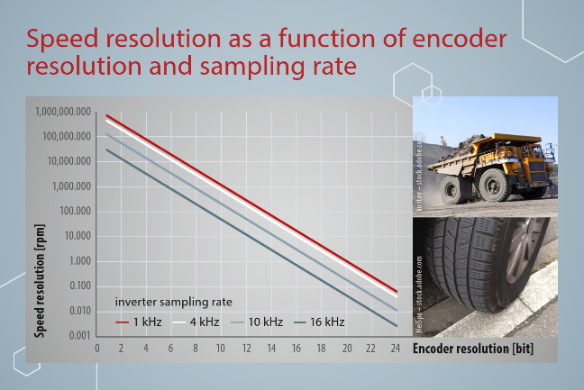
Figure 2: Correlation between sensor resolution, inverter switching frequency and speed resolution
Concept testing by using laboratory test bench
The laboratory test bench is shown in figure No. 3. It consists of a four-pole pair 48V PM-Motor, a controller capable to do field orientated control and a 48V battery system for power supply. Load torque is generated by a controlled brake system and is measured with a torque sensor continuously.
After doing test drives with the original sensor, the sensor was replaced by the new rotor position sensor, which has better accuracy and four times better resolution.
Based on this configuration we performed several test drives, like the simulation drives as shown before.
Figure No. 4 shows the slow acceleration drive results at high electric machine torque demand corresponding to vehicle high load.
On the left side of the figure, the current curve is shown as a red line at the top and the velocity curve is shown as a black curve at the bottom for the low resolution and low accuracy sensor, while the right side of the figure shows the same curves for the Lenord+Bauer sensor.
As a result, the test drive shows significant differences in the top diagrams orange current lines and the blue torque lines. The original equipped sensor leads to higher torque- and speed-ripples. This leads to more vibration and noise.
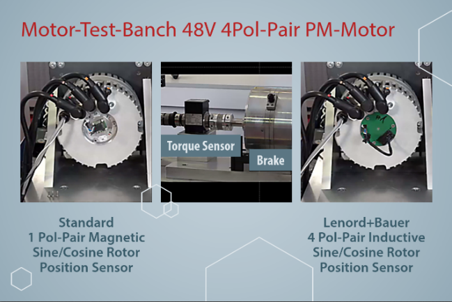
Figure 3: Test bench at Lenord + Bauer laboratory
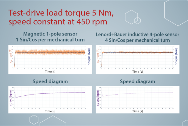
Figure 4: Slow, high load launch starting from zero speed, measured at test bench
4 WLTP Test drive
Figures No. 5 and No. 6 show the red torque curves when performing a WLTP like test-drive about 30 minutes. The drivetrain with the original sensor shows worse behaviour versus the Lenord+Bauer sensor.
The energy consumed could be reduced by 2.5%. The vehicle battery size could be reduced accordingly, or the vehicle mileage range can be increased by using same battery.

Figure 5: WLTP test drive sensor with low resolution and accuracy leading to energy consumption of 203.5 Wh

Figure 6: WLTP test drive Lenord+Bauer sensor with high resolution and accuracy leading to energy consumption of 198.6 Wh
5 Sensor and sensor error
The main signals of all used angle sensors in electric motors are sine and cosine signals, even when we are talking about resolver, magnetic or inductive sensors.
The calculation of rotor angle after digital-analog-converting is done with the formula… =arctang (sine / cosine)
Figure No. 7 illustrates that interrelation.

Figure 7: sine / cosine sensor output
The error main root causes regarding angle calculation are determined by the quality of sine and cosine signals, directly.
The following errors could occur:
a) Amplitude and amplitude synchronisation
b) Phase shift sine / cosine
c) Offset
d) Disturbance of signals due to EMC (electromagnetic compatibility) failure events
The first three errors are influenced by the shape of the sensor and motor components and their tolerances, as well as the accuracy of the assembly. The more precise the component and the assembly process are, the better the calculation result.
Based-on our experiences gained from mass production of heavy duty applications, electric machine components wear over lifetime. Therefore, a sensor system is needed which does not require high-precision mounting for cost reasons and maintains accuracy even if the sensor conditions, such as air gap and coaxiality, deviates over the lifetime.
In addition, the system must be robust against electromagnetic interference fields, as found in electric traction motors.
The new upcoming inductive sensor technology is very suitable to meet all the requirements of electric machine manufacturers as well as the demands of electric machine controls specialists, who look for precise and robust feedback signals to do the FOC.
Lenord+Bauer has developed that new rotor position sensor, called VarioCoder©, based on the technology presented.
6 Conclusion
The Lenord+Bauer VarioCoder© rotor sensor system in the feedback loop of modern field oriented controlled electric machines can have a significant impact to the vehicle level efficiency, performance, noise behavior and reliability.
[1] the text is an adapted extract from a document published to the audience of CTI SYMPOSIUM “Automotive Drivetrain, Intelligent, Electrified” Berlin 2022


