Different requirements for development, validation or back-to-back test benches.
1. The role of the electric drive in the range
Electromobility is picking up speed, and the trend is rising. Many manufacturers and suppliers are faced with the major task of implementing the system change. A large number of new electrically operated models will come onto the market in the next few years and require the appropriate testing capacities for the individual stages of the product development process.
With e-vehicles in particular, according to the drag coefficient (drag coefficient) and the installed battery capacity, the effectiveness and reliability of the drive train with the electric motor play an important role in the achievable range.
Electric motors offer many advantages over internal combustion engines. They have a wide speed and torque range. In most cases, a manual transmission in the vehicle can therefore be dispensed with. Electric motors can also provide their maximum torque immediately from a standstill. In addition, the efficiency is more than twice as high as that of diesel or gasoline engines.
Further advantages are their low noise emissions, compact design, low weight and, of course, the possibility of using the braking energy again to charge the battery during the deceleration phase.
A basic distinction is made between the types of motor between direct current motors (DC) and alternating current motors (AC), with AC motors being used almost exclusively in today’s electric vehicles.
The reason for this is that with AC motors compared to DC motors, higher speeds can be generated, the power density is much higher and they have a better degree of efficiency. In addition, the maintenance effort for DC motors is higher.
The AC motors receive their electrical energy from inverters, also known as converters. These power electronics convert the direct voltage from the battery into an alternating voltage with the appropriate shape and frequency.
When building a three-phase motor, three electromagnetic coils are arranged offset by 120 °.
These three coils are each supplied by a conductor voltage phase of a three-phase system. As a result, a magnetic field is generated in each coil with a time offset of a third of a period. A rotating magnetic field results from the individual coil magnetic fields. If a rotatably mounted magnet (the rotor) is placed in the center of this magnetic field, the rotating field causes the magnet to rotate.
With three-phase motors, a basic distinction is made between synchronous and asynchronous motors.
The difference lies in the way the rotor works. With asynchronous motors, the rotor follows the rotating field of the stator (spatially fixed magnet) with a time delay, i.e. asynchronously. With a synchronous motor, the rotor follows the specified frequency and the rotating magnetic field in the stator synchronously.
In the case of asynchronous motors, a distinction is made between two types, separately excited synchronous machines (FSM) and permanent magnet synchronous machines (PSM).
With the FSM variant, an electromagnet is also attached to the rotor, which is supplied with energy without contact via induction or slip rings. As soon as the rotor and the magnetic field of the stator run synchronously, a torque is created.
Electric motors are preferably integrated in the immediate vicinity of the axles they are supposed to drive. The mechanical coupling of the motors with the wheels is implemented in different ways, mostly via reduction gears and drive shafts or integrated into the wheel as a so-called wheel hub motor.
In the case of an e-axle, the motor, electronics and transmission are already integrated in one component that directly drives the vehicle axle. With the wheel hub motor, the motor is housed directly in the wheel within the rim. With this type of drive, the central motor unit as well as the drive trains and gears to the wheels are omitted.
2. The development test bench for the electric drive
Since the testing and optimization of the electric axle drives should take place in the early project phases and not just in the vehicle, tests are carried out on drive test benches through simulations of different, realistic driving situations.
Endurance tests and thermal investigations are intended to ensure the long-term suitability of the components used under a wide variety of climatic conditions.
Functional checks of the various hardware and software versions support the development progress. The characterization of the drive with the recording of various characteristics such as torque, speed and efficiency round off the versatile test tasks.
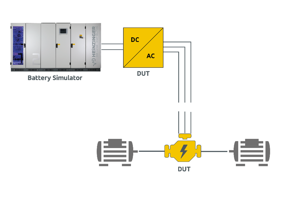
Depending on the version, a drive test bench typically consists of up to four brake machines, so-called “dynos”, which are connected to the drive / electric motor (s) via gears.
The vehicle’s energy storage device is simulated using a battery simulator. This supplies an inverter, which in turn generates a 3-phase AC voltage from the DC voltage of the battery. This alternating voltage then supplies the AC drive motors used in the vehicle.
According to the driving profile, the required speeds or torques are made available via the brake machines.
3. The battery simulation for the electric drive test bench
As already mentioned, the HV on-board network is simulated in the test bench with a battery simulation. For this typical application under conditions that are as real or ideal as possible, highly dynamic control of voltage, current and power as well as delay-free, continuous transitions between source and sink operation are essential.
To simulate real conditions, the power supply must be able to simulate the internal resistance of the battery in the simplest case (see Fig. 2).
Fig. 2
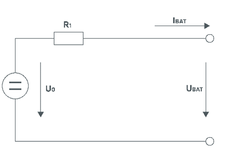
This requires fast algorithms that use the recorded current measured value to recalculate the dynamic setpoint of the voltage and pass this on to the control loop as a manipulated variable.
UBat=U0+(Ri*IBat)
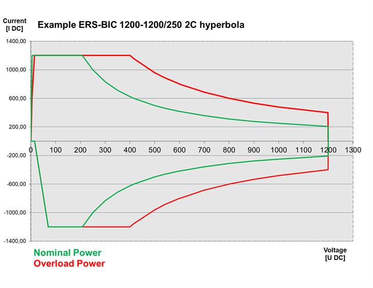
For the simulation of the state of charge (SOC = State of Charge) as well as the dynamic battery behaviour, further battery models should be available on the lowest layer in the system (see Fig. 3-5).


With these integrated models, in addition to the internal resistance, the state of charge of the battery can also be simulated.
The maximum power requirement of the battery simulator can be easily defined based on the energy requirements of the inverter / motor used and its losses.
In addition to the required nominal continuous output, short-term acceleration and braking processes with a corresponding overload must be taken into account when dimensioning the battery simulation.
For example, overloads depending on the required duration are an indication of what is technically possible today.
4. BACK-TO-BACK test benches for service life testing
If the next step is to check the service life of the motor / inverter components under different environmental conditions, these are often implemented with so-called BACK-TO-BACK test benches.
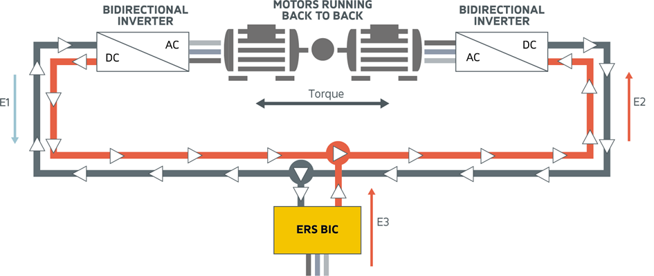
With this structure, two identical test objects are mechanically coupled to one another via an axis, which means that complex and costly brake motors are not required.
The block diagram shows the typical design of a “back-to-back” configuration of an inverter / motor test.
By changing the torque value of the two drives, one unit runs as a motor and the other as a generator. The power requirement of the test bench becomes clear if you consider the energy flow between the test objects and the battery simulator in the stationary state, because then it is a simple addition.
If the motor is running as a generator on the left, the result of the flow of energy is:
E2 = E1 + E3
(If the efficiencies of e.g. 5% for each motor are taken into account, the results are:
E2 = 105%, E1 = 95%, E3 = 10%)
If the motor on the right is running as a generator, the result of the energy flow is:
E1 = E2 + E3
In both cases, the only task of the battery simulation is to provide a stable output voltage and to compensate for the power dissipation of the system.
However, this simple calculation can no longer be used for the transient transitions that occur when accelerating and decelerating, as the gradient of the acceleration ramps, the inertia of the drives and delay times when converting electrical energy into kinetic energy and again electrical energy must be taken into account are. The data required for the calculation are usually not completely available because a test bench should usually also be designed for future engines.
The following rule of thumb can be used to dimension the required output power of the battery simulation, with which most test cycles can be implemented:
PERS = PMotor / 2
(e.g. each motor has an electrical power of 200 kW, the application requires an ERS system with a minimum output power of 100 kW).
In addition, a capacitor bank (e.g. 6mF) is often installed near the load for stabilization.
However, if the load changes are to take place with high dynamics, the energy requirement for the test bench can also briefly exceed the nominal power of a drive. This would either have to invest in a battery simulator with higher performance or a system that can be used with a very high overload capacity by default. The latter then saves costs overall.
5. CONCLUSION: COST OPTIMIZATION IN THE TEST BENCH
The big advantage of this type of test is the lower demands on the infrastructure.
There is no need to purchase the “Dynos” and the associated high investment costs. The performance requirements for the battery simulator are also halved, which means that the purchase price of this component is reduced at the same time.
The energy expenditure in the stationary area is limited to the losses of the test objects and the efficiency of the battery simulation used. This lowers operating costs. Two test items can be tested in parallel at the same time. The testing time is halved in terms of the number of pieces.
Limiting parameters in this test setup are the maximum torques, speeds and acceleration cycles of the test objects used.
Author: Albert Braasch Product Manager