Consistent e-Mobility analyses throughout the product development cycle
Innovative measurement solutions are needed to keep pace with the rapid development of electromobility. Tests and measurements in this area face special challenges. The new E-Mobility Measurement System from Vector and CSM was developed precisely to meet these challenges. In the following, it is explained using successful customer applications as examples of how this innovation has been deployed to increase powertrain and overall EV efficiency, and identify required changes prior to production approval.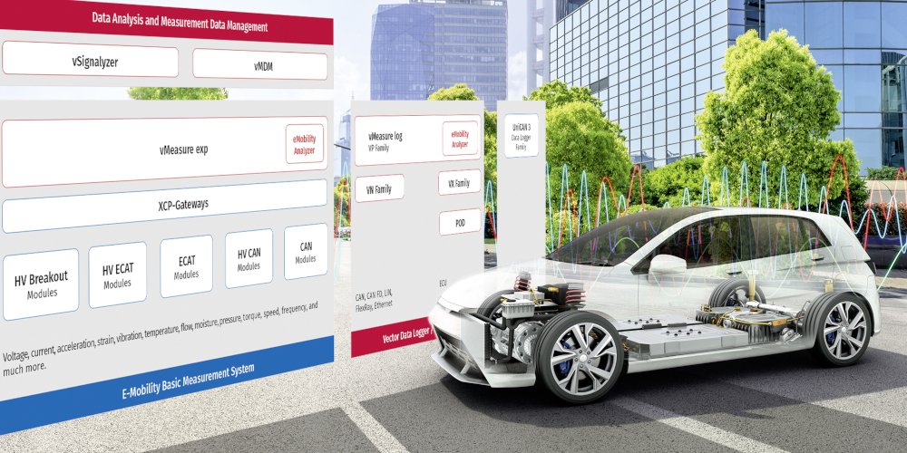
The challenges of measurement technology for electromobility
Automotive and other vehicle manufactures are working on operating systems and solutions with artificial intelligence. A few AI processors control all functions centrally. The algorithms deployed and the system components connected to them must be verified and tested for design improvements and final approvals. For this purpose, all physical parameters and vehicle characteristics should be measured and acquired synchronously in real time. One example is the investigation of high currents and voltages as well as their ripple for the verification of the high-voltage vehicle electrical system. At the same time, physical parameters such as temperatures, vibrations, and accelerations from components such as the battery, the powertrain, and other subsystems drawing energy from the main battery system must also be acquired and analyzed for both component and system optimization. During verification and for troubleshooting, it is important to synchronously acquire this physical measurement with the ECU-internal data and values communicated via the vehicle communication busses. In particular, high precision, multi-channel current, voltage and power analysis must be performed in real time to detect effects of driving maneuvers during road tests, for example to verify vehicle performance criteria or when following a standardized drive cycle for WLTP or EPA predictions. These systems involve potentially dangerous high-voltage and, therefore, safety for equipment and user must be ensured. For fleet tests, remote data logging and future-proof measurement data management are necessary.
 E-Mobility Measurement System from Vector and CSM
In cooperation, Vector Informatik and CSM have developed a new E-Mobility Measurement System to meet these challenges. Applications exist in all development phases for measurements, tests, and verifications for all types of electrified vehicles. The two companies’ competencies for software tools, algorithms and hardware measurement technology combine for an ideal system.
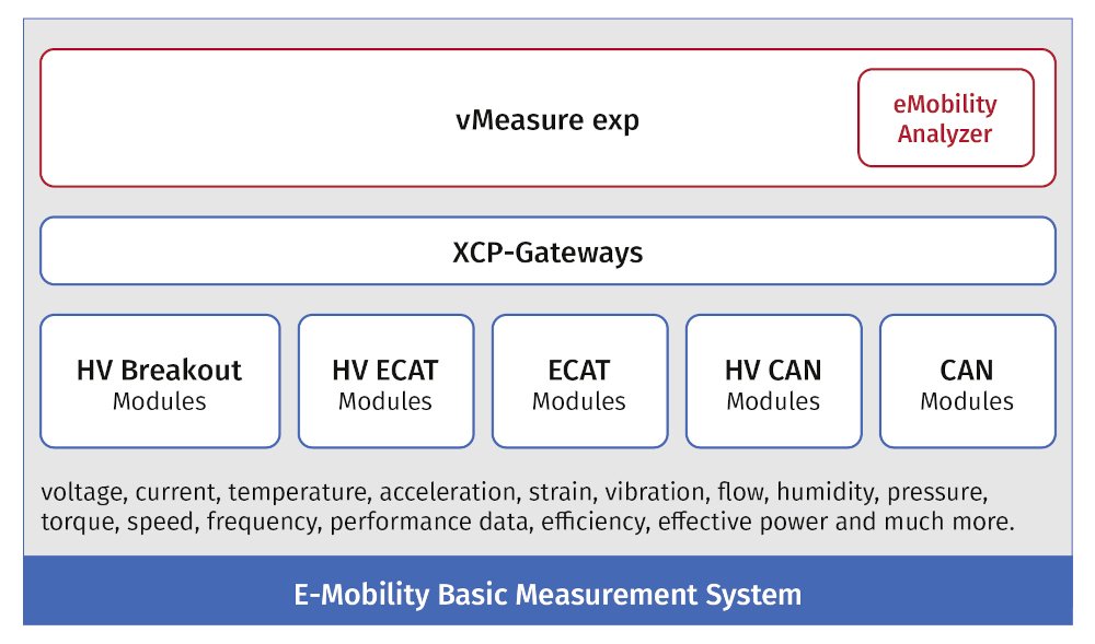
The E-Mobility Basic Measurement System allows the simultaneous measurement of all physical vehicle parameters as well as the real-time calculation of variables such as performance, efficiency, or energy consumption. Other analyses are also performed in real time, such as ripple, Fourier, or harmonic analysis.
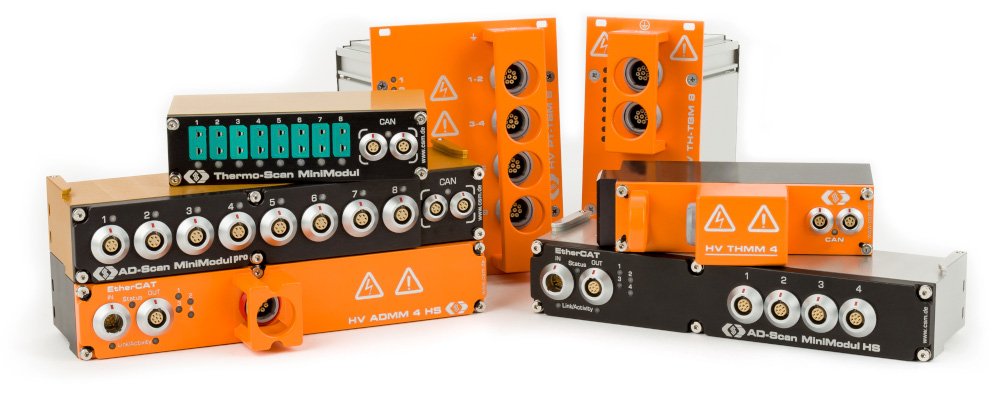
With the various small and robust CSM measurement modules, an application-specific measurement system can be easily configured and distributed around the vehicle to be close to the measurement sensors. Depending on the requirements of the measurement sampling rates, the measurement modules are networked via CAN and EtherCAT® (ECAT) communication busses, or a combination of both. The measurement data is transmitted to the Vector software, vMeasure exp or CANape via specialized XCP-Gateway which synchronizes all measurement data acquired better than 1 μs. This Vector software include the specially developed eMobilityAnalyzer, which is a library of functions that performs all real-time calculations of various powers, efficiency, and others.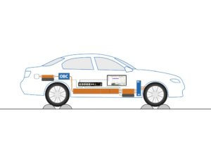
In this way, the energy consumption in a vehicle is measured with only three main measurement system components. If additional parameters are to be acquired, more measurement modules can be easily added to the measurement network.
eMobility Analyzer and HV Breakout Modules
The measurement of high currents, voltages, and powers in various locations throughout the vehicle is a fundamental requirement for electrification. The use of traditional measurement tools and approaches has proven to be inadequate for such a task: The classical power analyzers or tailored transient recorders are centralized devices, which are cumbersome to use, and are not designed to measure high voltages. The E-Mobility Measurement System allows high-voltage safe measurement with innovative HV Breakout Modules (HV BM) installed directly in the high-voltage cables. The inner high-voltage conductors are simply connected to the modules with terminal rings and the braided shield is applied to the module to assure continuity.
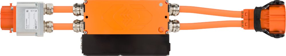
Special variants of the Breakout Modules are available for single cables, double cables, 3-phase and even to include precisely measuring shield currents.
The current and voltage sampling takes place synchronously inside the module and the sampled values are sent to the DAQ.
Several HV Breakout Modules are necessary to acquire all energy consumption data throughout the vehicle and its components. Figure 4 shows the simple setup for power and consumption measurement at a single location of a powertrain.
The two basic tools, a HV Breakout Module and the vMeasure exp software with eMobilityAnalyzer library, are used to measure physical values and calculate power, energy consumption or efficiency in real time. The application is quite simple: The HV Breakout Modules sample synchronously current and voltage at a high rate of 1 MS/s (1 Mega Samples per second). The values are used to calculate the power consumption or efficiency in real time. From the sampled values, vMeasure exp uses the eMobilityAnalyzer function library to calculate all power parameters in real time, such as active power, apparent power, reactive power, power factor or electrical work. The individual functions are precisely optimized for the measurement task:
| Application | eMobilityAnalyzer Functions |
| Efficiency of electric motor | Power analysis electric motor, mechanical motor power (speed, torque) |
| Efficiency of powertrain | DC power analysis, mechanical power axis (speed torque) |
| Efficiency of inverter | DC power analysis, input power electric motor |
| Efficiency of DC/DC converter | DC input power, DC output power |
| Power analysis electric motor | input power electric motor, star-delta transformation for phase currents and voltages |
| Energy consumption | Electrical work, ampere hours, DC power analysis, |
| Charging efficiency, charging power, charging energy | Effective power, electrical work, efficiency |
| High-voltage electrical system quality | Current / voltage ripple, characteristics of signal fluctuation, DC, and RMS values |
A central component of the power measurement is the determination of the electrical frequency or the speed as shown in figure 6. Simple methods for detecting the zero crossing deliver unstable results due to transients in the current signal. Therefore, integration over several periods is necessary. The model-based prediction approach implemented in vMeasure exp combines high dynamics with high stability. Thus, the active power can be calculated accurately for high velocity gradients as well as for constant velocity conditions.
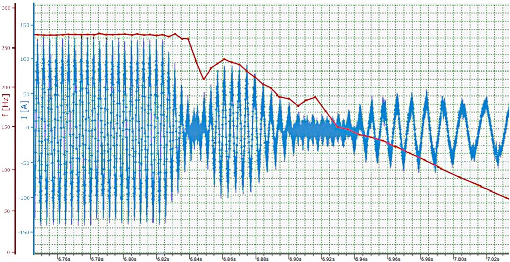 Measured current and calculated frequency
Measuring acceleration, temperature, and strain in high-voltage environments
The E-Mobility Basic Measurement System also includes measurement modules for the acquisition of all physical parameters such as temperature, humidity, vibration, acceleration, or speed. They are also networked via EtherCAT or CAN as appropriate for the sampling rate of the sensor used. Depending on the test object or application, conventional measurement modules or high-voltage safe measurement modules are used for this purpose. For high-voltage applications, standard sensors can be used, but they are connected to high-voltage safe sensor cables and measurement modules.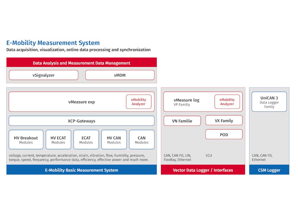
Vector CSM E-Mobility Measurement System
The E-Mobility Basic Measurement System is the heart of the complete measurement system, but not the whole system. As shown in Figure 5, other ECU interfaces, data logging, and data management components complete the entire system.
The additional data from ECUs can be acquired synchronously and recorded on data loggers for online or later analysis. This provides a finely scalable E-Mobility Measurement System that can be used in all development stages of vehicles in the test bench and in road tests. An important advantage lies not only in the immediate application of relatively simple measurements, the also in the possible expansion for complex measurement and validation tasks. This scalability offers security in adding any future innovations and protects the investment in such a system. Since Vector software tools are often used in development areas for ECU software, vehicle calibration or testing, another positive aspect is that little training time is required on the part of users. The E-Mobility Measurement System is continuously being expanded by Vector and CSM with further new application functions in cooperation with customers. Vector and CSM offer additional consulting services if required.
Johann Matha – Manager, emobility, CSM