The Devil Is In The Detail!
A Closer Look at a Multiphysics Fuel Cell Electric Bus Model
Much has been made recently about the importance of using virtual models in delivering eMobility. Benefits are often talked about in general and holistic terms; reduction of prototypes, digital twins, model-based design and so forth. As one can easily imagine, the accuracy of a model directly influences its usefulness. After all, you need to trust what the model is telling you in place of real-world testing. But how does a model achieve that realism? What is the importance of detail and fidelity? What benefits does complexity bring?


To answer that question, we need to understand simulation as a concept. Imagine a single use case and corresponding results dataset; we can quickly, and accurately formulate a model of some description which replicates that specific result. Such a model does not have to be a granular reproduction of all specific elements of the system, rather exhibit the same behavioural results compared to the use case. But we would not have confidence in applying the model to another use case. Without validation and adjustment of the model parameters that is, to satisfy the constraint of replicating enough real-world data sets to encompass all the use cases the model would likely encounter.
If we are building a model to simply replicate the results of real-world testing, then such an approach is satisfactory. We can define our model to behave in a way that we know is valid, therefore can consider our model to be valid as the outcome matches the validation condition. An important and useful concept. One could consider this model to be descriptive, and consistent with the definition of the word simulation.
However, there’s an immediate problem. We need to have results to validate our model against. A bit of a roadblock if we are trying to produce a model that is predictive – i.e. can be exercised without total validation results with confidence. Somewhat counterintuitively, what we need to do is produce a model which is more akin in sprit to an emulation – each element recreated in as much physical detail as possible. By building an overall model from a sum of valid parts, then we can create a predictive model which enables a non-existent physical system to be tested. Complex phenomena can then be observed, as all the combined interactions between components which comprise the system dynamics.
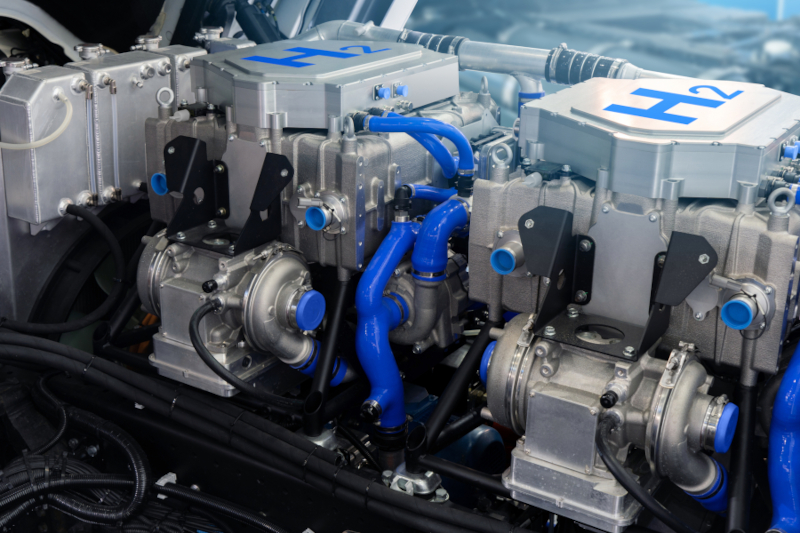
Such an approach can be very useful in the field of eMobility. Take the case of a hydrogen fuel cell electric (FCeV) bus. To produce a vehicle, multiple phenomena would need to be understood to integrate the fuel cell, equipped with the requisite ancillary systems. Traditionally this would require many cycles of an iterative design process, both costly in time and money. By producing a detailed high-fidelity model of the bus beforehand, much of the design work for specifying ancillary systems can be done virtually with confidence. Interplay between the control algorithm and the greater fuel cell system is of paramount importance. With a high-fidelity model, such an interplay is captured, enabling the control system to be optimised for each iteration of the design in turn. Estimations regarding the longevity and durability of the fuel cell can also be made, based on various metrics relating to parameters such as temperature gradients.
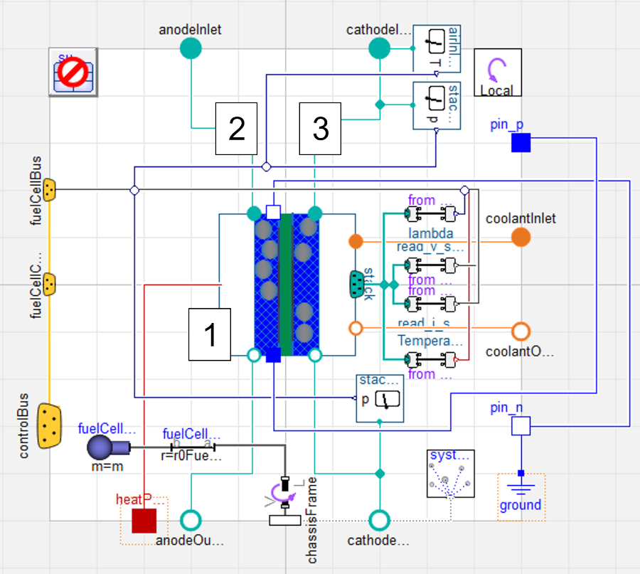
At Claytex, we recently produced such a model as a technical exercise. A particular type of FCeV was imagined, evolving from an existing ICE bus model. Coupled with a single 130kWh battery model, a single 125kW proton-electron membrane (PEM) fuel cell model using components from the Hydrogen library from Dassault Systemes, was created. Testing comprised of drive cycle analysis (SORT type) within a multibody model of a bus. Current production from the fuel cell is dependent upon the temperature and the pressure of the gases within. Using 1D fluids modelling within the ancillaries, an accurate representation of the dynamic conditions the fuel cell will endure can be captured. Each individual element of the ancillary system is included: the fuel tank, hydrogen recirculation circuit, humidifier, and purge valve (to manage mass fraction of oxygen in the anode) are included for the anode auxiliary system. Ambient air compressor, inlet heat exchanger, water recovery and exhaust valve (to maintain pressure across the cathode) comprise the cathode side ancillaries. Propylene Glycol coolant was used to cool both the heat exchanger and the fuel cell itself, in separate systems with heat rejected to the boundary. Fuel and aspiration systems featured pipe models, complete with the ability to reject, and absorb heat from the surrounding environment.

Small, detailed phenomena can be captured with such a model. With electro-chemical modelling within the stack of the fuel cell, the mass fractions of the gases within are calculated. As this is the case, important dynamics, such as the mass fraction of oxygen in the anode are captured. This can then be used to develop the control system for the purge valve on the recirculation system, to keep the fuel cell operating in the desired performance window. Not to mention, it enables the current production capabilities of the fuel cell stack to be understood at any single operating point, with the resultant effect on battery charge state, energy availability and drivability.
Thermal management of the fuel cell is critical; both excessive and insufficient temperature of the fuel cell will not only reduce the efficiency of current production, but also damage the membrane of the cell. By modelling the fuel tank, the freezing effect of hydrogen fuel expanding from the tank into the system can be included. This enables the correct countermeasures – usually a form of positive heat exchange with the incoming fuel – can be formulated. Vital to operation in cold ambient temperatures. Conversely, the effect of ambient heat (in warmer climates) can be studied, leading to more optimised control methods to be developed. Reducing energy being used on superfluous heating of the fuel will directly increase the efficiency of the system. Similarly, the need to cool the ambient air inlet into the cathode can be understood, due to compression causing a rise in the temperature. We can also see that heat flows from the cathode inlet to anode outlet of the stack in our model. As the anode gases are recirculated back into the stack, this dynamic directly effects the thermal performance, therefore the cooling needs of the stack.
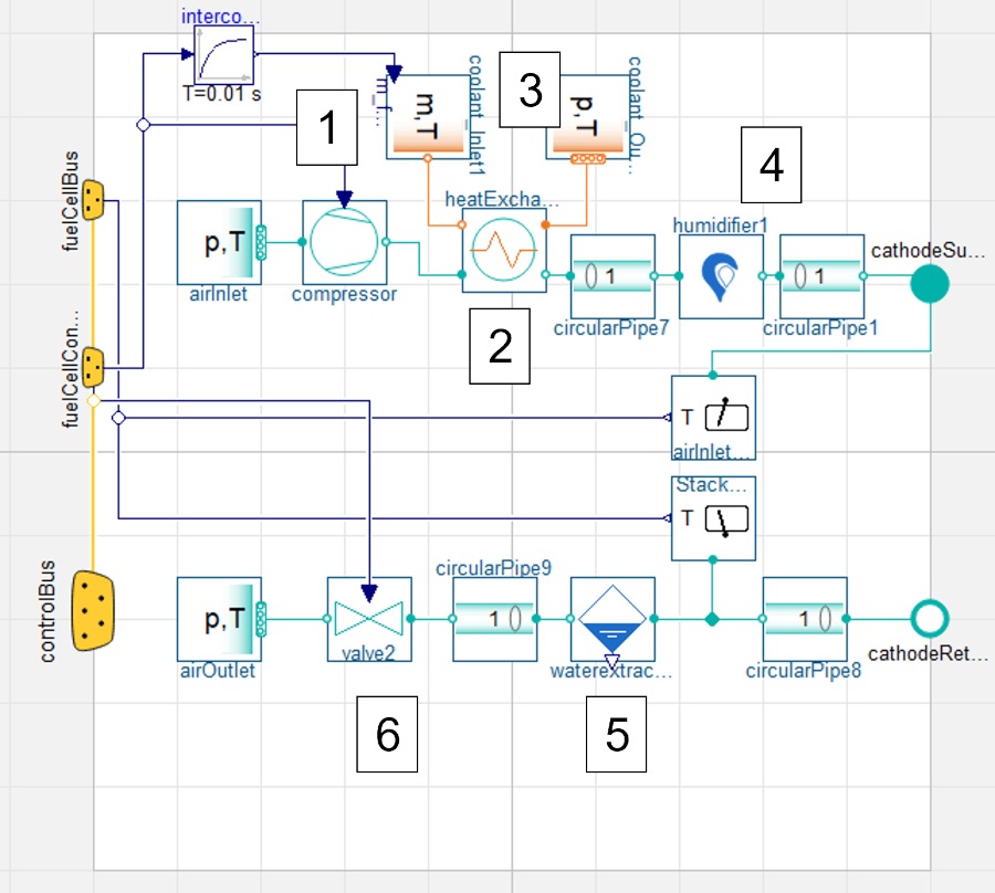
Even small details, concerning the internal pressure management of the stack, can be observed when analysing the results of the model. Hydrogen supply is increased due to demand; the purge valve (regulating the mass fraction of oxygen in the anode) also open more during demand events, indicative of a greater oxygen concentration in the anode as more reaction takes place. The action of the cathode exhaust valve corroborates this, as it closes slightly during demand events. Accruing to maintain pressure across the cathode, this indicates a pressure drop of some kind. Therefore, it can be theorised that there is gaseous loss towards the anode. A temperature gradient identified from the cathode inlet to the anode exhaust supports a theory of gaseous loss towards the anode in this manner.
By building a model in a modular manner from individual, validated components, a detailed high-fidelity model can be produced. Complex phenomena can then be observed; such phenomena which are difficult to capture in physical testing of full systems. Any minor observer effect induced by the instrumentation of the physical system is also eliminated. The devil truly is in the detail.
Theodor Ensbury, Project Engineer Claytex

