Safely Controlling an EV Traction Inverter
Antoine Dubois and Erik Santiago
Safety is the prime concern when designing electric vehicle (EV) inverters and their control systems. This article discusses the requirements and outlines an example solution using available control and monitoring ICs from NXP.
Traction inverters are a critical component in electric vehicles, not only for functionality but also for safety. The inverter has three-phase output drives for each hub motor, independently controlled for torque and speed. Under braking or ‘coasting’ conditions, the motors act as generators and the resulting power can be transferred back through the inverter for regenerative braking and to return energy to the battery. Safety concerns can be summarised as: unintended traction, unintended braking and danger of electric shock. In the automotive world, safety risks are classified by Automotive Safety Integrity Level (ASIL) according to ISO 26262,[1] ranging from ASIL-A to ASIL-D, the highest level, applicable to components or systems that, if they fail, could cause life-threatening or fatal injury. There is also a category QM, or ‘quality management’, for events that pose no automotive hazard. In this article, the hazard of electric shock is not considered.
Hazards and limits in EV applications
Typical safety limits for an EV traction system would be prevention of over-torque beyond 50Nm or +/-5% of requested value, or prevention of over-braking beyond the same limits. Both of these would be classified as ASIL-D hazards with a fault-tolerant time interval (FTTI) goal of 200ms – or the maximum time the system should take to transition to a safe state.
Figure 1 shows the simplified architecture of a drive for one motor. A typical control flow is as follows:
- A torque command is sent from the vehicle control unit (VCU) through a CAN bus connection.
- The torque command is received by the processing unit (PU).
- The PU computes the next pulse width modulated (PWM) signal for the inverter gate drivers according to torque demand and system state.
- The gate drivers cause the power switches to output phase currents to the motor.
- The PU monitors motor position, speed, phase currents and voltages along with fault indications to close the control loop and correct errors.

The scheme to achieve this control flow with appropriate ASIL safety levels will now be described using a solution from NXP which offers a suite of ICs intended for the application, based on the MPC5775B/E family of microcontrollers.
Control functions can be separated into ‘doing’ and ‘checking’
Failures in processing can be divided into communication and computation; the former is a function of the CAN connection and can be covered by standard integrity protection techniques in CAN commands. Failures in processing in the NXP microcontroller solution are monitored with a ‘doer–checker’ architecture, splitting the ‘doer’ main functional requirement, with its complex control algorithms such as field-oriented control (FOC) and computation, from the ‘checker’ function of fault detection and correction. The split arrangement avoids hazards of failure in one block affecting the other and allows more efficient allocation of processing resource. As all safety-related functions are with the ‘checker’ it must be ASIL-D qualified, but the ‘doer’ can be just QM-rated. Figure 2 shows the way the safety functions are split in a more detailed block diagram.

Figure 3 below shows the same functions but now indicating how they can be divided between the NXP MPC5775E microcontroller and the NXP FS65xx Safety Power System Basis Chip. This ideal combination implements the ‘doer’ in core 0 (non-lockstep) of the MPC5775E while the safety manager (checker) is implemented in lockstep core 1. Any possible common failure between the two cores is detected by internal mechanisms to the microcontroller such as clock monitoring and power management units, and externally by the FS65xx IC, monitoring clock, power, memory and software execution. The FS65xx also monitors the core 1 safety manager in the microcontroller with the ability to directly set the motor drive interface to a safe state. A range of library functions is available to implement the safety manager according to the NXP safety concept, for any particular safety runtime framework.

The permanent magnet synchronous motor interface – safety concept
A real-life situation is that when an EV brakes or coasts at speed, the inverter switches are all off and the motors generate a ‘back EMF’, causing regenerative current and uncontrolled braking torque on the vehicle. To prevent this hazard, the inverter reacts by closing all of its high-side or low-side switches to effectively short the motor windings (Figure 4).

To achieve this safely, a single-point failure must not make both high-side and low-side switch closure unavailable. This requires independent control for the high- and low-side switches.
Protection local to the inverter switches is also necessary in the case of short-circuits, which could damage the inverter bridge, leaving it in an unsafe state. The protection must be fast and cannot wait for the microcontroller to react, so requires current or anti-saturation monitoring directly at the switches. The NXP MC33GD31xx device, designed specifically for ISO 26262 ASIL-C/D, performs this function with a reaction time to short-circuits of less than 2µs for IGBT switches, and faster for SiC devices, with turn-off wave shaping to avoid the possibility of destructive voltage over-shoot. The device has galvanic isolation, comprehensive diagnostics and fault monitoring of over-current, over-temperature and under-voltage. For all faults around the inverter such as cooling loss and gate driver/discrete component failure, it autonomously manages and reports status via its INTB pin and redundant SPI interface. The IC detects switch failure and, depending on failure mode, sets the system to a safe state at high speed by setting either all high-side or low-side switches on together. The IC is also able to detect 99% of any internal faults with built-in self-test (BIST), a watchdog function and cyclic redundancy checks (CRC) for data. Faults reported back to the microcontroller safety manager function force a decision on which safe state is appropriate, and a command is relayed back to the MC33GD31xx device through a redundant ‘safe path’ in the IC, to directly act on the switch gate within the FTTI of 100µs. The arrangement is shown in Figure 5.

Safely closing the motor position control loop
To control the EV motor, phase current, angular position and battery voltage are monitored. Sensors used are clearly crucial to provide accurate information and must failsafe to avoid incorrect motor commands and resulting hazards. In the NXP inverter safety concept discussed (Figure 6), motor position sensing is assumed to be a mechanical resolver mounted on the motor shaft. Output is amplified and a software resolver (eTPU) analyses the complex timing events with the combination of a processor and timer channels. The eTPU is separated from core 0 and core 1 in the NXP MPC5775E MCU for safety and to avoid any computing load on the main motor control algorithm.

Figure 6: Motor position sensing in the NXP safety concept.
The flow of the process is:
- The resolver receives a high-frequency, sinusoidal ‘excitation’ signal provided by the eTPU within the MPC5775E.
- Two coils set at 90 degrees to each other in the resolver produce SIN and COS waveforms with 90-degree phase shift from the excitation signal, coupled through coils in the rotor. The relative amplitude of the two waveforms indicates angular position, and their modulation frequency represents speed.
- Sigma-delta ADCs convert the SIN and COS signals synchronously with the excitation signal, and results are stored in RAM for processing.
- Angle and speed are decoded from the demodulated signals using a ‘tracking observer’ model, with angle accuracy enhanced by extrapolation and correction for delay between acquisition point and end of processing.
- Angle and speed are passed to the motor control algorithm.
- In core 1 of the MCU, an ‘RDC’ block monitors the stages in the eTPU and performs diagnostics to check for a range of possible faults.
- An ‘input checker’ looks at raw values from the resolver to verify synchronisation of the excitation signal, maximum and minimum amplitude of SIN and COS signals and the ‘unit vector’, detecting 99% of hardware failures in coils, amplification stages, the excitation chain and A-D conversion.
- An ‘ATO checker’ computes rotor angle separately as a ‘plausibility check’ to detect failure of the eTPU and additionally cross-checks the angle extrapolation function in the eTPU.
The RDC checker block, with the motor interface, contains a library of safety functions which can be user-selected to adapt the MCU configuration to a particular application’s safety requirements.
Safe EV inverter driver designs are easy with support from NXP
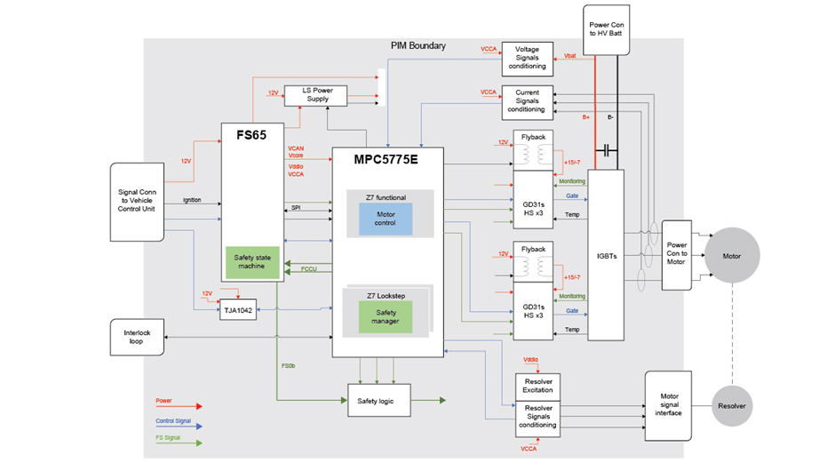
In this article we have considered safety requirements in three elements of an EV drive system, the motor control algorithm, motor interface and motor position, with examples of how the required ASIL level can be achieved with NXP microcontrollers, a safety power basis chip and intelligent gate drivers as in Figure 7.

Figure 7: Hardware safety concept
The concepts described are intended to be flexible and adaptable to customer requirements and have been implemented in hardware and software in the NXP EV Power Inverter Reference Platform: https://www.nxp.com/design/designs/ev-power-inverter-control-reference-platform:RDPWRINVERTER. An application-specific library is also available to help accelerate customer product safety development.
Antoine Dubois and Erik Santiago
Certified Functional Safety Experts, NXP Semiconductors
References
[1] ISO26262: ‘Road vehicles – Functional safety’
[/et_pb_text][/et_pb_column] [/et_pb_row] [/et_pb_section]


