Multilevel GaN inverter for highest HV EV performance and efficiency
Steffen Hahlbeck & Lukasz Roslaniec
Multi-level inverter is state-of-the-art today´s in electrical drive applications with high power and high voltages (e.g., electric power plants) or in applications which require a good quality of sinusoidal currents (e.g., photovoltaics inverter). With the trend of higher voltages and power demand in automotive electric drivetrains, these advantages become valuable for automotive main traction drives, too. The generated significant demand for power components, which comes with electrification of the automotive industry will continue its growth for the next decades. Parallelly, the efficiency of battery energy usage is critical for the cost and performance of electric cars. Gallium-Nitride-based components, which are superior to competing technologies, are undermining the long reign of silicon in the power world.
Speaking of multi-level inverter, more sinusoidal currents (lower total harmonic distortion – THD) reduce harmonic losses in the e-motor, support the NVH characteristics of the electric drivetrain, improve the EMC behaviour and therefore also reduce the stimulation of bearing currents. This reduced THD is generated by the additional voltage level of +/- UDC/2 in the output voltage to e-motor compared to 2-Level type inverter.

Figure 1: Comparison of output voltage to the e-motor
All these effects are well known from the textbook. In the recent years hofer powertrain developed an IGBT based NPC 3-Level inverter as part of a 3-in-1 system with an induction motor and a gearbox. Based on this electric drive system the different effects were investigated in great detail.
Especially, the improvement of the e-motor efficiency is of high interest for the automotive industry, since this results in less cooling demand and increased performance as well as driving range. The investigations for a 170-kW induction motor conducted by hofer powertrain show that e-motor losses in WLTP drive cycle can be reduced by 25%. Such an outstanding improvement cannot be achieved by any other measure for efficiency improvement.
When looking at NVH characteristic, measurements on e-motor side showed that “Lautheit” can also be reduced by about 25%. In the same magnitude improvements of EMC behaviour were observed. These “side effects” can either be used to reach a higher level of requirements for the electric drive or can be considered as a degree of freedom to reduce efforts within EMC filter of the inverter, NVH damping of the electric drivetrain or countermeasures on bearing currents.
Of course, this improvement comes at the cost of additional effort in the inverter. Due to the multi-level topology additional switches become necessary. hofer powertrain chose for the 3-Level inverter the Neutral Point Clamping (NPC) topology to reduce the requirement of breakdown voltage for the power switches from 1200 V down to 650 V at a battery voltage of up to 950 V. Other additional effort needs to be considered for the DC link capacitor and the gate drive board.

Overall, this results in a minimal increase of inverter volume and more power switches in the power path. This demands a careful selection of these power switches. Todays automotive IGBT power modules with breakdown voltage of 650 V provide a good power to cost ratio but show a rather poor efficiency from automotive point of view, especially when combined in a 3-Level inverter. In the end a reduction of the efficiency improvement gained by the e-motor on electric drive system level can be observed.
Another opportunity is a Silicon Carbide (SiC) based power switch or a hybrid solution out of IGBT and SiC switches and diodes. For such a configuration the efficiency of the inverter will be comparable to a state of the art 2-Level type inverter based on SiC power switches for WLTP drive cycle. Main drawback for a SiC configuration is the high costs for the power switches regardless of the topology.
To find the best solution, hofer powertrain has been investigating the use of Gallium Nitrite power switches for the use in a 3-Level inverter.
Gallium Nitride (GaN) power devices have shown great promise in providing high-efficiency power conversion. The unique structure of wide bandgap GaN semiconductors creates devices with remarkably high transport characteristics and charge density in the channel, operating at high voltages. These characteristics allow the devices to be used at much higher frequencies and with fewer parasitics. Inherent in these unique characteristics is flexibility in device design to enable the robust operation and high performance.
Not all Gallium Nitride transistors are the same. There are two implementations of lateral GaN power devices: a normally on or depletion mode (D-mode) device and a normally off or enhancement (E-mode) device, and each device has its advantages and disadvantages. The gate region is quite different for these two implementations and plays a critical role in the potential reliability. Understanding these trade-offs are necessary to make a proper choice for an application.
VisIC Technologies‘ D3GaN technology (Direct Drive D-Mode) was developed for the high-reliability standards of the automotive industry and offers the lowest losses per RDS (on). It also simplifies the system and enables highly efficient and affordable powertrain platform solutions. This solution reduces the cooling system requirements and the size of the electronic car’s inverter; thus, EV Cars can save 50% on inverter power losses over the electric car’s driving cycle, reduce battery cost and increase driving range. The ability to support vehicles with an 800V and 400V battery is a significant step forward in GaN worldwide adoption by the automotive electrical driveline.
For inverter applications, the ability to parallel GaN devices is paramount, and the D3GaN topology was a-priori designed to support device paralleling. With the direct access to the GaN gates and positive temperature coefficients, along with the already highest current rating per die (i.e., 200Amp), this solution paves the way to the simplest GaN system implementation that meets the high-power demand of the automotive market.
An exciting system development, aimed for 800 V application, is utilizing the proven 650 V rated devices in a 3-Level Inverter. This design showcases GaN devices’ capabilities to improve 800V Electric Motor systems by lowering the phase current ripple and improving drive cycle efficiency. With lower total losses versus the standard 2-Level approach, the D3GaN power switches offer the best utilization performance and TCO.
hofer powertrain and VisIC technologies recently announced the news regarding a traction inverter with D3GaN technology that run successfully in lab tests.
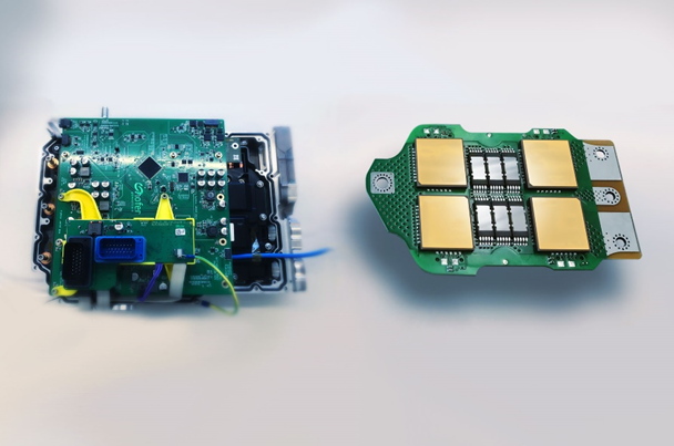
In 2022 hofer powertrain realized a first lab sample of a 3-level NPC inverter based on GaN discrete power modules with a current rating of 100 Arms. This lab sample supports the upcoming development of an A-sample in 2023 which shall be able to reach state of the art current ratings for automotive electric main drives and show the full potential of combining 3-L inverter topology with GaN on electric drive system level.
Especially in Commercial Vehicles, Motorsport vehicles, Hypercars and eVTOLs the use of Multilevel Inverter technology is beneficial already today. Within these applications high power demand and reduced sensitivity for inverter BOM costs result already today in an improvement of the electric drive system on vehicle level compared to the 2-Level type. With the introduction of GaN power switches more applications will follow.
Lukasz is Head of Power Electronics Department and Steffen is the Manager Business Development Electric Drive at hofer Powertrain