Fuel Cell Powered Electric Vehicles – Meeting the Optimization Challenges
Electric propulsion for light and medium duty vehicles has been well established for some years, with energy storage focussing almost entirely on batteries (BEVs). As markets and missions expand, not all use cases are well suited to BEVs – commercial vehicles combine intensive use and long journeys, leading to pressure to reduce recharging time. Supply issues, such as battery materials, are also of concern as demand continues to grow.
For many tasks, the unique capabilities of fuel cell vehicles with electric propulsion are more attractive than the battery powered alternative, with advantages including refuel times comparable to conventional ICE vehicles and light weight energy storage compared with batteries. Depending on fuel source, fuel cell electric vehicles (FCEV) have the potential to offer very low or even zero carbon emissions.
The cost of the battery in a BEV represents a substantial proportion of the total cost of the vehicle, which becomes increasingly significant when scaling for higher mileage capability. Hydrogen storage can be scaled far more cost effectively where space constraints allow, leading to comparative cost savings for larger (e.g. commercial) vehicles.
Fuel cell technology isn’t just limited to one market segment. Various OEMs already have fuel cell vehicles on the market and many more have prototypes under development with specific applications and users in mind.
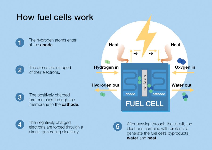
Fuel cell technology has been used in high-cost applications (such as space flight) since the 1960s, but recently developments have seen the viability of lower operating temperature proton-exchange membrane (PEM) fuel cells which are well suited to automotive applications. The fuel cells operate by reacting hydrogen and oxygen to produce electricity, with several hundred fitted into a typical automotive stack. These stacks operate most efficiently at approximately 80°C and therefore can be cooled with conventional vehicle thermal systems with a few challenges. The coolant must be non-conductive and therefore specific fluids must be used in conjunction with an ion exchange filter. Further challenges relate to the reduced temperature at which the vehicle can reject heat when compared to their combustion engine counterparts.
How fuel cells work.
Modern PEMFC stacks have higher efficiencies than automotive internal combustion engines (ICE) – typically in the range of 50-65%. As with an ICE, additional equipment for fuel and air handling, is required to provide the reactants to the fuel cell, known as balance-of-plant (BOP). The BOP components form a parasitic load which reduces the overall system efficiency and provides an opportunity for optimization and development.
Typically, the air is provided via an electric compressor, fuel by a gas injector and heat is removed by liquid cooling system. Additional components, such as: air control valves, air humidifiers, anode recirculation systems, turbines, charge-coolers, water separators and purge systems are used to increase efficiency at the cost of system complexity and physical size.
The stack itself operates most efficiently at higher cathode and anode pressures but this creates higher parasitic losses from the air system. Ideally the stack should be well humidified to minimize ohmic losses across the proton membrane but not excessively such that liquid water can form and block the gas diffusion layer. High cathode stoichiometry, a measure of ‘excess’ oxygen, also improves efficiency by ensuring hydrogen ions can readily bond with oxygen but this requires higher compressor flows and increased pumping power.
Similar optimization can occur on the anode loop. Purge duration and frequency must be balanced to maintain high efficiency and prevent water build up, whilst avoiding excessive hydrogen loss. For systems equipped with recirculation pumps, high flow rates can improve efficiency of the stack but at the cost of pumping losses, similar to the cathode loop.
The correct hardware choice and best operating condition are a complex optimization trade-off which can only be achieved by a mix of proper component selection and sizing, architecture considerations, advanced controls, experimental verification and tuning – treating the entire BOP as a system.
With growing demand for testing facilities to support this optimisation and development, UK based e-powertrain consultancy CamMotive have recently put into service their new facility for hydrogen fuel cell testing. The dedicated test site is already in use for projects to evaluate and optimize the next generation of hydrogen fuel cell technologies for use in transportation and stationary power applications.
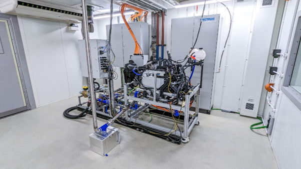
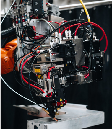
An automotive fuel cell, developed by Ford, under test at the test facilities. The stack and balance of plant can be packaged into the space of an internal combustion of comparable power.
Bruce Campell, Director of CamMotive explained “Our objective was to create a test environment to support and accelerate the development cycle for new hydrogen fuel cell technologies, including hardware and control system optimisation.”
“We’ve combined world-class test capability and infrastructure with decades of expertise in powertrain testing and development to help our partners deliver the most sustainable hydrogen-fuelled solutions for road, air, rail and sea transportation and stationary power.”
The company has developed bespoke software to control the fuel cell test environment and measure key metrics including electrical power output, thermal output, hydrogen usage and emissions. Data from these tests are used to evaluate component behaviour and overall system performance and allow optimisation for efficiency, transient response, safety and service life.
The development of the test facility was initiated as part of the company’s role in a consortium led by Ford to build a small fleet of prototype hydrogen fuel cell versions of its electric E-Transit commercial vehicle. The three-year FCVGen2.0 project was announced in May 2023 and is part-funded by the UK Government, via the Advanced Propulsion Centre (APC) Collaborative Research and Development programme.

Fuel cell systems developed by Ford and currently being tested, will be installed into Ford E-Transit donor vehicles to assess their suitability for high daily energy demand use-cases, where battery electric vehicles lack onboard energy or charging opportunities.
The team at CamMotive have been exercising the Ford designed system through the power range by operating steady state, load-steps and dynamic drive cycles. In addition to meeting the specific requirements of the project, the test environment has been developed to serve the wider hydrogen fuel cell market in the UK and around the world.
Bruce highlighted the benefits of involvement with the FCVGen2.0 project “Being part of the consortium has given us access to generous and valuable industry expertise that has allowed us to build our fuel cell test capability more quickly. We’ve used data from tests run on the Ford-designed hydrogen fuel cells to optimise the control system and validate hardware designs.
“The launch of our new test facility marks the latest phase of our development to support and advance the viability of hydrogen technologies. Our next step is to expand our test infrastructure, including additional test cells and a flexible fuel cell stack and balance of plant evaluation platform to meet the demands of the clean energy market.”
CamMotive believe that component manufacturers, who are developing BOP components, such as electrical compressors often lack full system testing opportunities to validate and refine their designs. The team at CamMotive, supported by FCVGen2.0 Project partners, Viritech, are developing a fuel cell system that provides a fully flexible platform for hardware and software innovations to be rapidly tested. New technologies, such as water tolerant turbines, suitable for the low temperature fuel cell operation, can incrementally improve the efficiency of the system. However, issues like water management provide a challenge to their use in real operation and their system allows suppliers to effectively test and explore these difficult conditions.
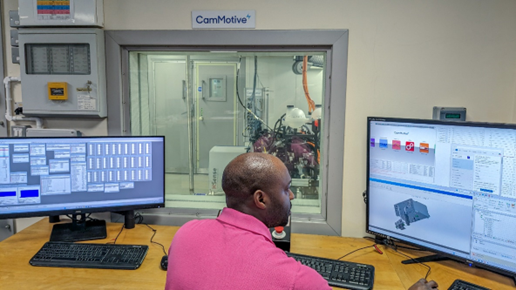
A flexible fuel cell and balance of plant to support component and software development. Full control of the system operating parameters can be using its rapid controls prototyping hardware.
The software which operates the fuel cell can be adjusted and redeployed in minutes, using a dSPACE rapid prototyping platform. Being able to adjust the control algorithms and operating conditions, such as the operating pressures, air-to-fuel ratio, purge frequency and temperatures provides value data for component and system engineers alike.
Dr Paul Dickinson Technical Specialist CamMotiv