New fast switching Silicon Carbide (SiC) Power Transistors are now widely available as discrete devices or bare die. Their low on-resistance at high blocking voltages, high switching speed and thermal performance allows system engineers to achieve significant gains in size, weight and efficiency for motor drives and battery chargers whilst anticipating a continuous drop in SiC devices pricing. However, an important brake for the adoption of SiC in high power applications is the availability of well-optimized power modules as well as the learning curve in reliably driving them. Intelligent Power Modules answer both challenges by offering highly integrated and plug-in-play solutions accelerating time-to-market and saving engineering resources.
This article discusses the benefits of selecting CISSOID’s 3-Phase 1200V SiC MOSFET Intelligent Power Module (IPM) scalable platform for power converter designs in E-mobility applications. This low-loss technology offers a fully integrated solution including a 3-Phase water-cooled SiC MOSFET power module with built-in gate drivers. This article not only presents the electrical and thermal characteristics of the power modules but also discusses the support they bring to fully benefit from SiC advantages. There, a key element is the gate driver and its ability to drive safely and reliably the SiC MOSFETs.

Low losses & enhanced thermal robustness translate into higher power density
CXT-PLA3SA12450 is part of a scalable platform ranging from 300A to 600A per phase. This 3-Phase 1200V/450A SiC MOSFET IPM features low conduction losses, with 3.25mOhms on-resistance, and low switching losses, with 7.8mJ turn-on and 8mJ turn-off energies at 600V/300A (see Table 1). It cuts losses by at least a factor of three with respect to state-of-the-art IGBT power modules. The module is water-cooled through a lightweight AlSiC pin-fin baseplate for a junction-to-fluid thermal resistance of 0.15°C/W. The power module is rated for junction temperatures up to 175°C while its gate driver operates up to 125°C ambient. The IPM withstands isolation voltages up to 3600V (50Hz, 1min).
Table 1. CXT-PLA3SA12450 3-Phase 1200V/450A SiC MOSFET Intelligent Power Modules Main Characteristics
| Parameter | Conditions | Typ. | Max. |
| Drain to Source Voltage | 1200V | ||
| Continuous Drain Current | VGS =15V, TC=25°C, Tj<175°C | 450A | |
| VGS =15V, TC=90°C, Tj<175°C | 330A | ||
| Static drain-to-source resistance | VGS =15V, ID=300A, Tj=25°C | 3.25mOhms | 4mOhms |
| VGS =15V, ID=300A, Tj=175°C | 5.25mOhms | ||
| Turn-On Switching Energy | VDS=600V; VGS= -3/15V; IDS = 300A; L = 50µH | 7.8mJ | |
| Turn-Off Switching Energy | 8mJ | ||
| Isolation | AC @50Hz (for 1mn), baseplate – power pins | 3600VAC | |
| Junction-to-Fluid Thermal resistance | Each switch position, Flow rate: 10l/min; 50% ethylene glycol, 50% water, 75°C inflow temperature | 0.15°C/W | |
| Junction-to-Case Thermal resistance | Each switch position | 0.13°C/W | |
| Operating Junction Temperature | 175°C | ||
| Baseplate dimensions | 104mm (W) 154mm (L) | ||
| Weight | 580g |
3D models & trusted thermal characteristics enable fast power converter design
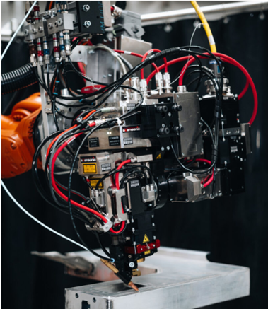
A great benefit of this IPM is the high level of integration of the power module with its gate driver and cooling AlSiC pin fin baseplate. This allows a rapid mechanical integration with the other elements of the power converter such as the DC bus capacitor and the cooling system as shown in Figure 2. The system designer may save a lot of time having access to an accurate a 3D model of the IPM including the gate driver right from the very beginning.
Having the conduction and switching losses of the power module fully characterized together with a fully optimized gate driver reduces the thermal design space and possible iterations in the optimization of the power converters.

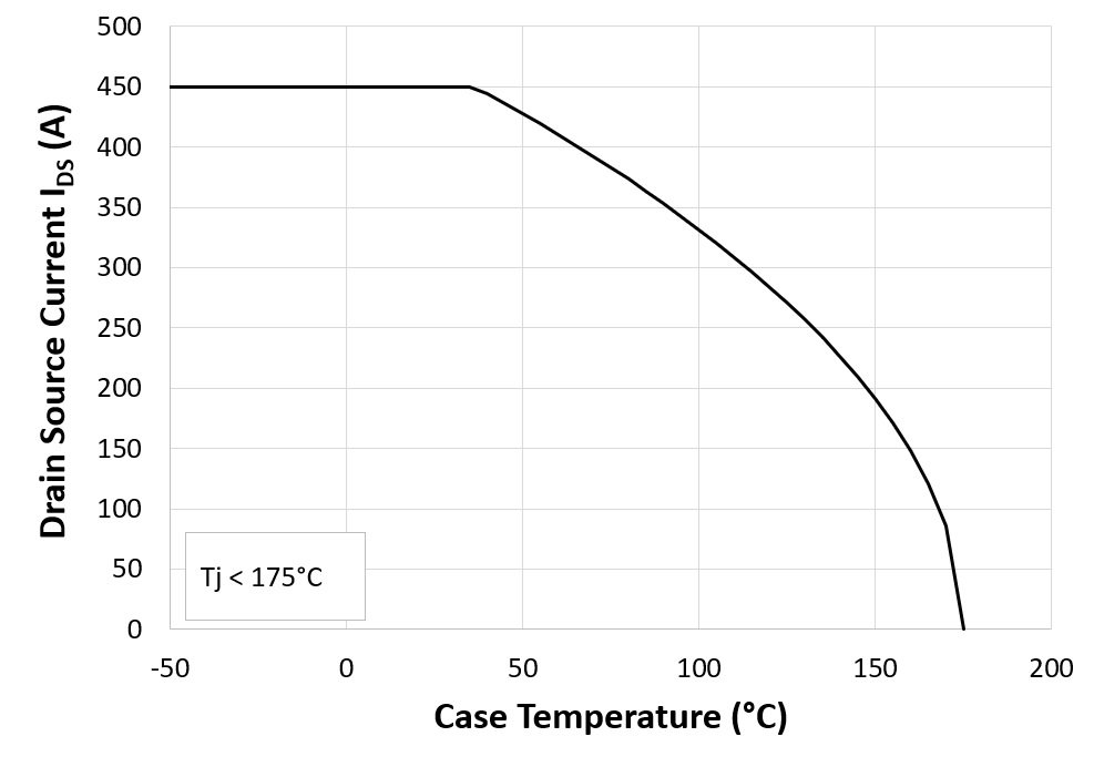
Based on the junction-to-fluid thermal resistance of 0.15°C/W per switch position, with a flow rate of 10l/min (50% ethylene glycol, 50% water) and an inflow temperature of 75°C, the maximum continuous drain current derating versus the case temperature can be calculated. This is based on the on-resistance at maximum Tj, and the maximum operating Tj, and is shown in Figure 3.
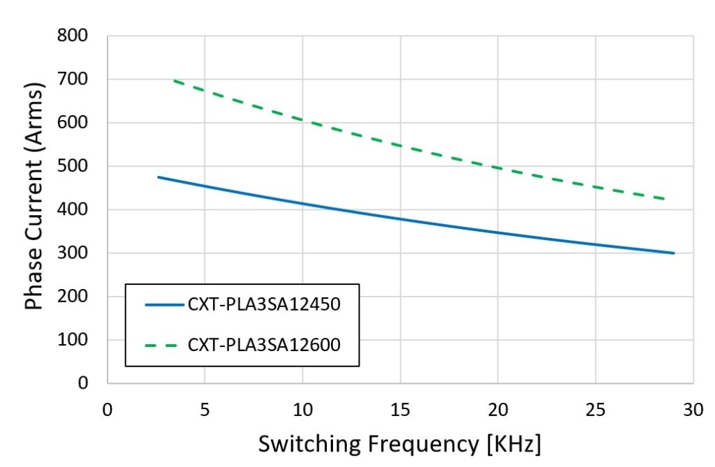
If the maximum continuous drain current is a standard characteristic useful to compare the current rating of power modules, a more realistic Figure-of-Merit (FoM) is probably the RMS phase current versus the switching frequency as shown in Figure 4 for the CXT-PLA3SA12450. It is calculated for a DC bus voltage of 600V, case temperature of 90°C, junction temperature of 175°C and 50% duty cycle. This FoM is more useful to understand the applicability of the module. With this Intelligent Power Module platform being scalable, Figure 4 also extrapolates the safe operating area of 1200V/600A module (dashed line).
Robust SiC Gate Drivers enable fast switching and low losses
The CXT-PLA3SA12450 3-phase gate driver leverages on the experience gained with single-phase SiC gate drivers, e.g. CMT-TIT8243 [1, 2] and CMT-TIT0697 [3] designed respectively for 62mm 1200V/300A and fast-switching XM3 1200V/450A SiC MOSFET power modules (see Figure 5). The 3-phase gate driver has been optimized to fit on top of CXT-PLA3SA12450 power module thanks to a more compact transformer module or creepage distances compliant with pollution degree 2. The CXT-PLA3SA12450 gate driver also includes a DC bus voltage monitoring function.
As for CMT-TIT8243 and CMT-TIT0697, the CXT-PLA3SA12450 gate driver board has been designed for a maximum ambient operating temperature of 125°C. All the components have been carefully selected and sized to be suitable for operation at this temperature. It also relies on CISSOID’s high temperature gate driver chipset [4, 5] and a power transformer module optimized for low parasitic capacitance (10pF typically) to minimize common mode currents at high dV/dt and for high operating temperature.

The CXT-PLA3SA12450 gate driver still has headroom to support the power module scalability. The module has a total gate charge of 910nC. At 25KHz, the average gate current is equal to 22.75mA. This is well below the 95mA maximum current capability of the on-board isolated DC-DC converter. The current capability and gate charge of the power module can thus be increased, without gate driver board modifications. With the populated gate resistors, the actual max dV/dt is in the range of 10 to 20 KV/µs. The gate driver has been designed to be immune to dV/dt up to 50KV/µs, offering margin in terms of dV/dt robustness.
Gate Driver Protections improve system functional safety
Gate Driver protection functions are critical to guarantee the safe operation of the power module. This is particularly true when driving fast-switching SiC transistors. The CXT-PLA3SA12450 gate driver offers the following protection functions:
- Undervoltage Lockout (UVLO): CXT-PLA3SA12450 Gate Driver monitors primary & secondary voltages and reports a fault when below a programmed voltage.
- Anti-overlap: avoids simultaneous turn-on of both high-side and low-side to prevent short circuit of the power half bridge.
- Protection against any short-circuit at secondary: isolated DC-DC converter cycle-by-cycle current limitation protect the gate driver against any short-circuit (e.g. gate-source short-circuit).
- Glitch filter: suppresses glitches on incoming PWM signals which might be due to common mode currents.
- Active Miller Clamping (AMC): implements a bypassing of the negative gate resistor after turn-off to protect the power MOSFETs against parasitic turn-on.
- Desaturation detection: at turn-on, checks after blanking time that the power MOSFET drain-source voltage is below a threshold.
- Soft Shut-down: in case of fault, a slow turn-off of the power transistor is implemented to minimize overshoots due to high dI/dt.
Conclusion
Silicon Carbide (SiC) Intelligent Power Modules (IPM) provide system designers with an optimized solution accelerating their power converter design. The co-integration of driving and cooling functions offers trustable electrical and thermal characteristics from the start reducing the long learning curve often associated with this still relatively new technology. This new scalable IPM platform will support new adopters of SiC technology for E-mobility applications.
References
[1] CMT-TIT8243: 1200V High Temperature (125°C) Half-Bridge SiC MOSFET Gate Driver Datasheet : http://www.cissoid.com/files/files/products/titan/CMT-TIT8243.pdf
[2] P. Delatte “A High Temperature Gate Driver for Half Bridge SiC MOSFET 62mm Power Modules”, Bodo’s Power Systems, p54, September 2019
[3] CMT-TIT0697: 1200V High Temperature (125°C) Half-Bridge SiC MOSFET Gate Driver Datasheet : http://www.cissoid.com/files/files/products/titan/CMT-TIT0697.pdf
[4] High Temperature Gate Driver Primary Side IC Datasheet: DC-DC Controller & Isolated Signal Transceivers http://www.cissoid.com/files/files/products/titan/CMT-HADES2P-High-temperature-Isolated-Gate-driver-Primary-side.pdf
[5] High Temperature Gate Driver -Secondary Side IC Datasheet: Driver & Protection Functions http://www.cissoid.com/files/files/products/titan/CMT-HADES2S-High-temperature-Gate-Driver-Secondary-side.pdf