Facing the Challenges of EV Powertrains with Driveability Engineering
The new challenges to vehicle development that electric powertrains entail call for further development of proven development and testing systems. IPG Automotive presents an enhanced powertrain-in-the-loop development environment and a suitable workflow that enable efficient development, testing and calibration of new software functions and their effects on the total vehicle system.
The automotive industry is in a state of transition toward electric mobility. With its new electrified fleet, a brand can differentiate itself from other manufacturers based on the electric driving experience [1], among other things, because driveability decisively contributes to brand experience.
Going forward, the calibration of electric powertrains in terms of ride comfort and dynamics will therefore become even more important than before. Because electric motors offer response and control behavior that is many times faster than that of internal combustion engines, the prerequisites for such calibration are excellent. In addition, the mechanical transfer from the motor to the tires is clearly stiffer in their case, enabling the tire’s longitudinal slip to be adjusted a lot more directly and precisely than in the past.
Moreover, it will be possible to implement robust torque shaping algorithms on the power electronics of electric drive units (EDUs) in the future. Due to their extremely high frequency in the upper kHz range, they can realize the desired acceleration behavior on full-vehicle level almost exactly. They enable a near-complete correction of interferences and minimization of potentially damaging load reversal impacts on the component. Typically, the limiting factor in this case is not the drive system but the transmission of power to the road via the tire. In this way, the vehicle’s brand-specific DNA can be defined by means of software and its calibration. Hence this is another area reflecting the trend toward software-defined vehicles.
1. The Development and Test Environment

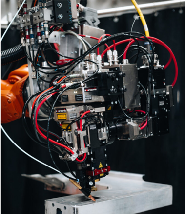
Figure 1: Development and test environment
The development and test environment on which this article is based is shown in Figure 1. Here, the EDU with the motor, transmission and power electronics as its subcomponents has been integrated as a real-world component (real Unit Under Test, rUUT). It is extended by virtual components (virtual Unit Under Test, vUUT) and virtual real-time-capable models of future real-world components (real-time simulation models). This refers to hardware, such as the tires and chassis, as does the virtual driver and the envisioned operating range of the vehicle (Operational Design Domain, ODD). The virtualized powertrain and vehicle dynamics controllers of the full vehicle are relevant as well. When the vehicle, as depicted, has another electric axle but the test bed has only two dynos, this axle is operated as an additional virtual component in the full vehicle. The vUUTs are run practically without dead time with a total delay of less than 0.25−1 ms on the CarMaker/TestBed platform. To enable investigations of the questions that are relevant to driveability on a test bed of this design, the breadth of the total system including dynos and the secondary control loop should cover the range 0−20 Hz without phase shifting. Furthermore, the dynamometers should have high dynamics and correspondingly large power reserves so that the wheel units can be used for mapping dynamics effects. An integrated battery simulator helps to fully investigate electrified powertrains and to map interactions between power electronics, energy storage and drive. The real-time-capable, high-resolution HIL simulation is realized based on the Xpack4 system via Ethercat/UDP (1 kHz). The test campaign and online analysis of the KPIs can be run on the platform as well. In addition to the established development fields of energy efficiency and operating strategy, questions relating to vehicle dynamics, ride comfort and NVH can thus be investigated on the same test bed without any additional effort.
2 Setting up target-driven virtual vehicles
Managing the longitudinal dynamic vibration behavior of motor vehicles is one of the oldest and most important tasks in the field of machine dynamics [2]. Sudden changes in drive torque – which, among other things, are caused by the driving maneuvers described in Figure 2 – excite longitudinal vibrations in the total vehicle that are superimposed on its mean acceleration.

Figure 2: Basic driveability driving maneuvers and variation variables in the test catalog
The lowest of these vibration frequencies is referred to as vehicle shuffle. By way of example, Figure 3 shows that the gear-dependent natural frequency of the mechanical system is typically below 12 Hz. The speed-dependent damping ratio (according to Lehr) is in the range of 0.05 to 0.13.

Figure 3: Dependency of the natural mechanical shuffle frequency and Lehr’s damping ratio as a function of vehicle speed during a tip-in maneuver on a dry (dark blue) and a wet (light blue) road. Depicted by way of example as a box plot (median, quartiles, and 5 % respectively 95 % quartile (as a whisker) from 20 test runs).

Figure 4: Objective driveability attributes (KPIs) of the tip-in and drive-away driving maneuver, respectively.
The objective attributes, depicted in Figure 4 by the example of the tip-in and drive-away (vehicle launch) maneuver, are not only perceptible by humans but may also be perceived as very unpleasant. Various human organs – such as the stomach – have natural frequencies in this range and may therefore start to resonate during respective maneuvers.
At the same time, a slow torque increase, which would cancel those vibrations, leads to sluggish responsiveness of the vehicle, and thus reduced acceleration.
The attributes in Figure 4 can be influenced directly by torque shaping, i.e., by software functions and their calibration. For the target-driven virtual vehicle setup, various key statements can be captured as described below.
Setting the vehicle target on natural frequencies of the mechanical system
A successful development process requires utmost clarity about the targets to be achieved and how to achieve them. The variables depicted in Figure 3 are, by definition, determined by the mechanical system. They result from the elasticities of the suspension subframe, the driveshafts, the tires and the chassis, plus the damping characteristics and mass ratios of the assembly components. Comparable, for instance, with the planned total mass of the vehicle or its projected coast-down performance, these are not variables that emerge incidentally during the development process, but are fundamental, pre-determined and documented targets (including optimal values and limits) of vehicle development that are to be achieved in the development process. Targets are set primarily as part of a superordinate process of vehicle development. Target setting requires in-depth corporate and competitive benchmarking and a customer market profile. In the case at hand, it largely results from differential considerations of the previous model [3].
The virtual prototype passes through a quality gate before it can be used in the area of driveability engineering. This process includes an advance analysis of whether the stated targets (lowest natural frequency/damping) match the projected target vehicle. Further targets, such as total mass, basic tire parameters, etc., are additionally checked as part of the quality gate.
Adapting the vehicle driveline shuffle
For a driveline test bed to form a suitable work environment for driveability applications, certain prerequisites must have been met. The vehicle driveline shuffle properties (mass ratios, longitudinal slip and relaxation length of the tires as well as natural frequency and damping rate of the lowest longitudinal dynamic natural vibration) that have previously described and are specified by the mechanical setup must match – with adequate accuracy – the vehicle targets that have been set in advance or are known a priori.
The following analogy may serve to understand the relevance of this statement with greater clarity: It is a well-known fact that the tractive resistance of a vehicle has a decisive effect on its energy efficiency. Consequently, a development method – for instance, to optimize an operational strategy for energy efficiency – only makes sense on a dynamometer if the models used represent the tractive resistance targets precisely. Due to the relevance of this subject for type approval, legislators had to define this process very robustly. As a result, it encompasses not only an exact definition of what KPIs are to be used for characterization (i.e. the target coefficients f0, f1 and f2 of a polynomial) but also exact specifications of how these KPIs are to be used for parameterizing a vehicle that qualifies for use on a dynamometer. Based on clearly defined quality criteria, the virtual prototype is tested for suitability for the planned purpose – the optimization of an operating strategy. This total process is also referred to as coast-down adaptation [4].
Therefore, the analogical conclusion is that in the context of driveability the vehicle driveline shuffle adaptation has the same relevance as the coast-down adaptation does in the context of energy efficiency. Notably, in both cases only the virtual mechanical setup is the object of the adaptation but not software, functions, or their calibration. Consequently, the software-defined vehicle is not affected by this. For that reason, a suitable process was defined and so-called interface models were provided to support this work.

Figure 5: Method for developing driveability on a dynamometer
4. Conclusion
Based on the integrated toolchain and method presented in this article, a driveability calibration can be performed on a dynamometer. Driveability investigations about longitudinal dynamics and the subsequent application effort in the vehicle development process can be front-loaded in this way, enhancing flexibility and agility in the calibration process many times over. Safety-relevant and typically time-intensive road tests can be run reproducibly with reduced effort on a dynamometer. Compared to real-world road test measurements on a proving ground, basic application tasks can be performed on a dynamometer multiple times faster.
Dr. Felix Pfister, IPG Automotive GmbH
Nico Hetzel, IPG Automotive GmbH
Literature
[1] M. Rasch; H. Schmidt: Interview with Audi Group CEO Markus Duesmann, Neue Zürcher Zeitung, 2021 [Online], Available: https://www.nzz.ch/wirtschaft/audi-chef-autoproduktion-und-umweltschutz-sind-kein-gegensatz-ld.1631817, last accessed 2022/04/26
[2] O. Frahm: VDI. Zeitschrift des Vereines Deutscher Ingenieure, Bd. 46, 1902, S. 797
[3] Krammer, S.: How to Define Your Vehicle Performance Targets. MAGNA, Complete Vehicle Insights, March 2022 https://insights.apps-magna.com/how-to-define-vehicle-performance-targets
[4] ISO 10521-2:2006: Road vehicles — Road load — Part 2: Reproduction on chassis dynamometer, 6.1.1.4 Adjustment, 2006