by Lorenz Roos, Senior Application Engineer, Maglab AG, Switzerland
With the electrification of mobility and the transformation towards renewable energies, batteries are becoming an essential part of high availability and reliability systems such as energy grid storage and e-mobility vehicles. Representing a major share of the system cost; battery efficiency, energy density, and lifetime requirements are ever-increasing, pushing for constant innovation in the battery technologies. State of the art high energy density batteries used both in the e-mobility and energy sector; require specialized Battery Monitoring Sensor (BMS) to cope with the application and safety requirements.
Current sensing has long been an important function implemented by BMS, to protect batteries from abuse and trigger safety shutdowns when operated in over current. Now, however, requirements for current sensing are becoming much more stringent. In particular, industry-standard high energy density batteries such as Lithium Iron Phosphate (LFP) or Lithium-titanate (LTO) show stable output voltage as a function of their capacity particularly in their utility range, requiring coulomb counting to determine the State of Charge (SoC), State of Health (SoH) and State of Function (SoF) of the batteries.
The SoC is of particular importance for Electric vehicles (EV) manufacturers constantly working on improving the performance and safety of their battery systems. Specially, range anxiety is one of the biggest friction points of the electrification of the mobile park, pushing not only for higher density batteries with increasing thermal runaway and stringent requirements but also accurate SoC measurements enabling the BMS to optimize battery efficiency and operation for long cycle life.
Sensing Technologies
Conventional current sensors used to measure the SoX solutions are based on Hall or shunt technology.
Shunt current sensors measure the voltage drop across a precision shunt resistor to determine the current flowing through the shunt. This resistive measure, although offering very interesting dynamic ranges and linearity, does have some limitations at high currents and at low currents. At low currents, the output voltages of the sensor interfaces, may be clamped and therefore over-estimating the currents. Active compensations such as voltage offset or current injection can overcome such technology limitations and therefore, improving the low current measurement specifications. Whereas at high currents the resistive power dissipation in the shunt starts to be a thermal issue.
Magnetic current sensors are contactless, providing galvanic isolation, no power dissipation and enabling faster readout. At the same time, the offsets arising from the unbalanced measurement bridge, and temperature and stress effects, can be corrected via active feedback loops, adjusting the gain parameters and actively compensating the sensor offset thanks to combinatory readout measurements.
These solutions diversities, not only on technology but also in terms of required active compensation make them very suitable for a redundancy measurement for functional safety application. In particular, in the automotive and high-density energy storage industry, BMS are facing rising functional safety requirements. The combination using both technologies, shunt and magnetic, becomes increasingly attractive. Not only providing redundant measurement of the current but also strengthening the system diversity and therefore reducing common faults and silent latent faults.
Maglab developed a platform approach, in order to accommodate different customer current sensing requirements while reusing the same module architecture and therefore increasing the reliability at lower cost. Such a platform relies on the combination of a shunt and contactless magnetic field sensor consisting of ferromagnetic shield and xMR or Hall sensor.
The module assembly relies on the proper dimension on the one hand the shunt balancing accuracy versus thermal performances and on the other hand the laminated U formed (LU) magnetic shield, where magnetic saturation at high current and footprint have to be balanced. Based on this and the market demand, three standard designs have been proposed (see Figure 1).
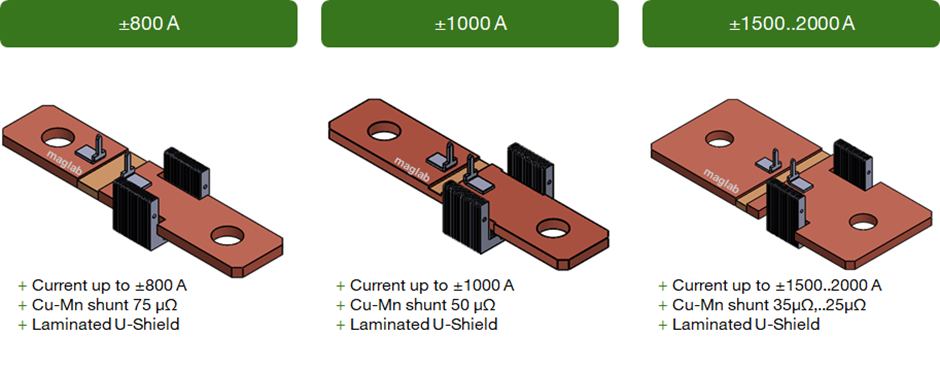
Figure 1: Sub-assemblies of different shunts (75 µΩ, 50 µΩ, 35µΩ left to right) with laminated U-shields.
Further to the sub-assemblies, universal readout electronics (Figure 2) was developed to measure both the magnetic and the shunt channels. The readout electronics provide not only the amplification chain but also the required high voltage isolation for the shunt up 4 kV, a configurable microcontroller and a CAN interface.
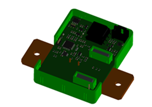
Figure 2: BMS module and electronic PCB with high voltage isolation

The detailed system level diagram of the readout electronics are shown in Figure 3. As it can be seen, particular attention has been given to the safety and redundancy of the design. In particular for signal processing, the external high speed 18 bits ADC allows the high accuracy readout of the shunt voltage measurement, redundant and independent to the internal 12 bit ADC used for the Hall measurement. Both converted signals are then processed at the microcontroller where after filtering, a safety check is performed and an error signal is raised in the event of discrepant values above a configurable threshold. Both current measurements can be output via the CAN interface, meeting the system level safety requirements.
Furthermore, thanks to the onboard capabilities of the microcontrollers, additional features have been included in order to increase the system accuracy and performance. An onboard multi point calibration and zero offset compensation can be easily programmed, accounting for non linearities and module-to-module divergences. In addition, an on-PCB temperature sensor located on top of the shunt allows easy thermal bridging and therefore accurate thermal compensation. Thanks to all the active compensations, a total 1% resolution full range over lifetime can be achieved. Such temperature can be directly outputted via the CAN interface.
A battery voltage measurement is done via a probe connection to the other polarity of the battery using a galvanic isolated pin connection. Such voltage can be directly outputted via the CAN interface.

In order to cope with the constant expansion of the electrification market and its evolving requirements, new efforts are being made to further develop the current sensing platform. The particular focus for the upcoming generation will be to reduce its overall footprint, adapt it for higher volume requirements and increase the choices of interface.